Structures Laboratory
The Structures Laboratory Eindhoven is well-equipped for testing structural elements, components and systems of various materials. The laboratory experiments for fundamental research are mainly performed in order to calibrate finite element models for simulating the structural behavior of the specimens.
The Structures Laboratory Eindhoven is well-equipped for testing structural elements, components and systems of various materials. The laboratory experiments for fundamental research are mainly performed in order to calibrate finite element models for simulating the structural behavior of the specimens. This allows the researchers to perform parameter studies with the help of finite element computer programs with the ultimate goal of developing design rules and guidelines for the structural system under investigation.
Research Facilities
- 2 Cranes of 5000 kG (total 10000 kG)
- Facilities to prepare specimens or test accesoires
- Digital Control Systems to operate Hydraulic jacks
- Measurement equipment to scan and store sensor data
- AccelerationTemperatures and humidity
- Strains
- Deformations (Analog - Digital and Optical (ESPI = Electronic Speckle Pattern Interferrometre)
- Forces
- Sensors to measure
- Climate controlled rooms 9 * 12 meter and 2 * 2 meter
- Variable system to construct test setup
- Hydraulic pump system (20 and 80 liters/min to control hydraulic Jacks
- Tension tests up to 400 kN
- 250 kN Tension - Compression machine Instron
- 100 kN Tension - Compression machine Schenk-Instron
- 250 kN Tension - Compression machine Schenk-Instron
- 400 kN Tension - machine Schenk-Intron
- Compression tests up to 5 MN
- 4 MN Compression machine Form + Test
- 2.5 MN Compression machine Schenk - Instron
Electromechanical Machines
Hydraulic Machines
Projects
The Laboratory owns dedicated data-acquisition systems as well as more general systems for controlling and monitoring experiments. Depending on the character of an experiment a choice can be made between a wide range of sensors with its own specific range and accuracy
A variety of Data Acquisition Systems are available in the Laboratory. Depending on the Desired Accuracy, Sample speed, Amount of sensors in an experiment and type of sensors Laboratory Staff will advise which system to choose. Typical maximum specifications are:
- Up to 18 bit resolution
- Up to 666 kS/s Input
- Up to 2.8MS/s output
- Up to 156 Sensors in 1 system (limitations in type of sensors).
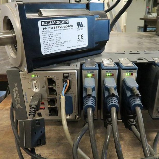
cRIO controller used for motion sytems in the Active facades research.
MOOG and Instron systems to control Hydraulic cylinders.
For most experiments standard Lab software is suitable, for special measurement and control functions dedicated software can be developed. Also special tools are available to monitor vibrations, measure accelerations and process image Acquisition.
Data acquisition
Measurement principle
Test conditions
If ESPI is required, the test conditions have to be determined.
Some important boundary conditions and properties:
- Maximum surface area 20 * 20 cm
- Minimum surface 3*3 mm (macro mode)
- Surface has to be optically rough
- Vibrations can cause bad measurements or instability of the test setup, a room with no vibrations is preferred. Vibrations generated by the test itself must be damped if possible
- ESPI measures the displacement difference of a surface, if body motion occurs it is difficult to determine small displacement differences, as well as the strain in the measured area (special test setup with attachment of the ESPI-head to the material can be a solution)
- If an experiment contains more than one material with a different optical reflection, no uniform illumination is possible, special spray is available to prepare these specimens
- Export facilities are available for post process of data.
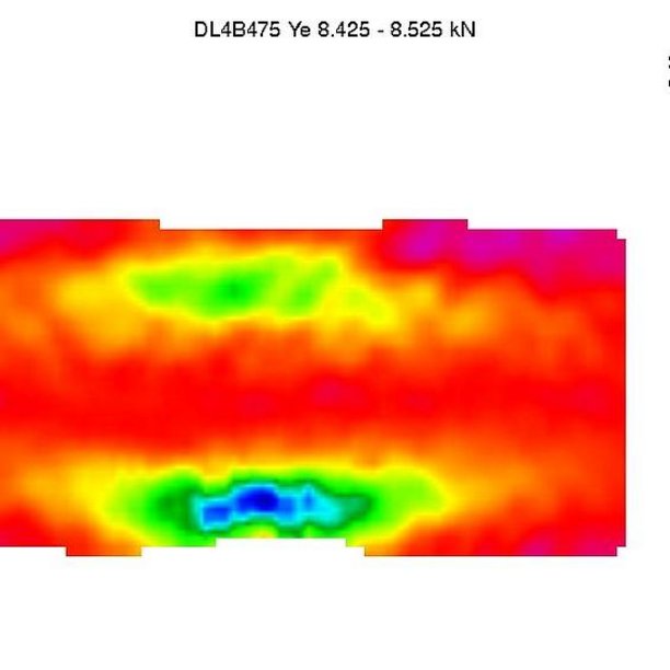
The surface of a specimen is illuminated from two positions with coherent laser light in various phases of testing.
The speckle interferometry uses the interference characteristics of electromagnetic waves. It is based on the fact that an optically rough surface appears granulated when it is lit by an coherent light (laser). This phenomenon is called a speckle and the individual grains are termed speckle.
After each load step, the reflected light is captured with a CCD camera. At first a speckle pattern is found, which includes the deformation information of each point of the measured object. By subtracting speckle patterns from various phases of testing, interference fringes are formed. The number of fringes and their widths are a measure for the displacements of the illuminated area.
3D-Displacement and strain distribution can be determined with a resolution of 10 nm or 1 µm/m.
Automatic evaluation of the measurement by real-time subtraction and phase-shifting algorithms is possible. Changing the polarity of the laser, displacements in X, Y and Z direction can be obtained. To compare speckle patterns and to establish strains from measured displacements special computer software is available.
Contact
-
Hans Lamers